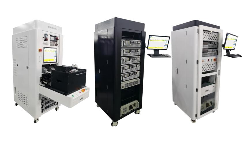
System Introduction
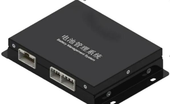
The Battery Management System (BMS) is one of the most important components of a lithium battery pack. BMS not only monitors battery voltage, current, temperature and other parameters in real time, but also takes into account leakage detection, thermal management, battery balancing management, alarm reminders, SOC calculation, SOH status reporting and other functions during battery charging and discharging, so that the battery is always in a safe and controllable charging and discharging process, greatly improving the cycle life of the battery during actual use. Therefore, each BMS manufacturer attaches great importance to the detection of BMS research and development, testing, production and other links.
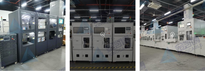
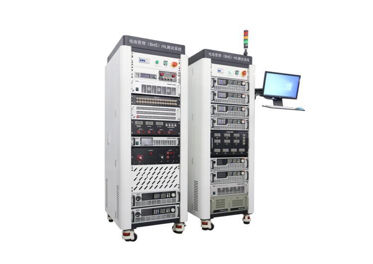
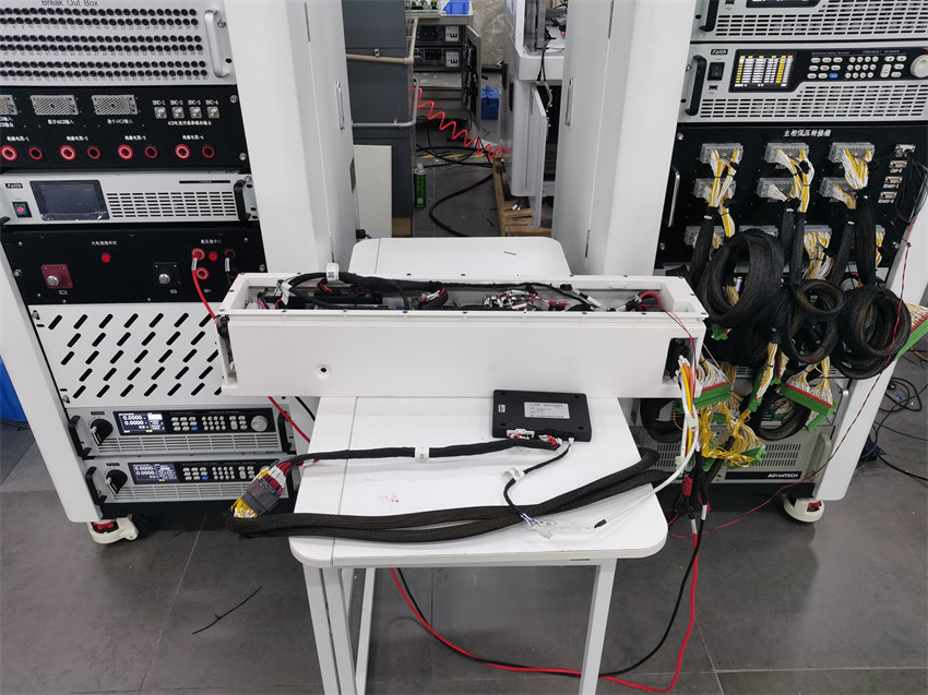
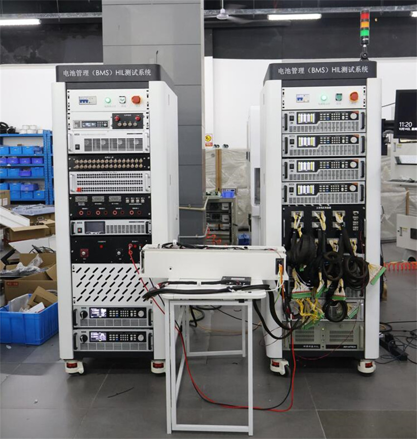
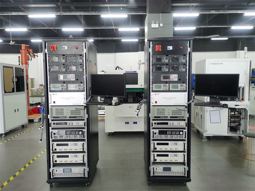
The BMS offline EOL (End of Line) test system is a device that performs final tests on the battery management system (BMS) production line to ensure that all performance and functions of the BMS meet the design requirements before delivery. The following are some of the main test functions of the system: (Test functions can also be customized according to actual customer needs)

1. Power supply and electrical function test
Power supply working current test: detect the current consumption of the BMS under different working conditions to ensure the normal power management function.
Total voltage and total current test: measure the total voltage and total current of the battery pack to verify the voltage and current acquisition accuracy of the BMS.
Insulation resistance test: use an insulation tester to detect the insulation performance of the battery pack to ensure the safety of the battery system.
AC and DC withstand voltage test: simulate the working state of the battery pack under extreme voltage conditions to test its withstand voltage capability.
2. Communication function test
CAN communication test: verify the communication function between the BMS and the vehicle control unit or other modules to ensure the accuracy and stability of data transmission.
Wake-up test: detect whether the wake-up function of the BMS is normal to ensure that the system can be correctly awakened in low power mode.
CC/CC2/CP test: Test the communication and control functions of the fast charging interface to ensure the safety and reliability of the charging process.
3. Battery parameter and status detection
Cell voltage acquisition test: Simulate the voltage change of the battery cell to detect the acquisition accuracy and balancing control function of the BMS for the cell voltage.
Temperature simulation and detection: Provide signals under different temperature conditions through the temperature simulator to verify the temperature monitoring and protection functions of the BMS.
Analog input and output test: Detect the analog signal input and output functions of the BMS to ensure that it can accurately collect and process sensor signals.
4. Fault diagnosis and protection function test
Fault injection and diagnosis: Simulate various fault scenarios (such as overcharge, over discharge, short circuit, etc.) to test the fault detection and protection capabilities of the BMS.
Relay control and adhesion detection: Detect the control function of the BMS on the relay, and the adhesion detection capability of the relay under abnormal conditions.
Insulation detection function test: Verify the insulation detection and alarm functions of the BMS by changing the insulation resistance value of the battery pack.
5. Charging and discharging function test
Fast and slow charging docking test: simulate fast charging and slow charging scenarios to verify the charging management function of BMS, including the compatibility of charging protocols and charging efficiency.
Charging and discharging circuit test: detect whether the charging and discharging circuit of the battery pack is normal to ensure the safety and reliability of the current path.
6. Software and system function test
Software and hardware version number reading: verify the software and hardware version information of BMS to ensure the consistency and traceability of the system.
PWM wave test: detect the PWM signal output function of BMS to ensure that it can accurately control related equipment.
Data acquisition and recording: the test system can collect and record the operation data of BMS in real time, and support data storage and analysis.
7. Automation and expansion function
Automated test process: the system supports automated test process, can automatically start the test, judge the results, and generate detailed test reports.
Modular design and expansion: the system adopts a modular architecture, which can flexibly configure the test module according to different needs, and reserve expansion interfaces.
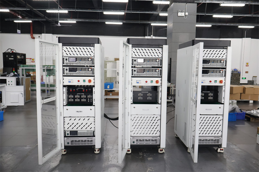
It can be widely used in BMS manufacturers, power vehicles and energy storage manufacturers, power tool manufacturers, scientific research and third-party testing institutions, etc. It can quickly meet the FCT testing of BMS production line PCBA, BMS research laboratory EOL functional testing, BMS aging testing and other types of BMS project testing needs. The BMS test equipment realizes modular and standardized design, and can realize rapid batch standardized production, which can meet more than 90% of BMS testing needs on the market.
Test function
BMS Test Items | Test Method |
State detection accuracy test | Adjust relevant parameters such as temperature, current, single cell voltage, total voltage, insulation resistance, etc., compare the standard values with the parameters obtained by the battery management system (BMS), calculate the BMS temperature, current, single cell voltage, total voltage, insulation resistance measurement errors and the maximum, minimum and average values of the errors to obtain the accuracy of each parameter. |
SOC accuracy test | Adjust the battery simulator to simulate according to the battery test condition curve. BMS estimates the battery SOC capacity based on the detected data to test the SOC accuracy of BMS. |
Battery Diagnostic Test | Inject faults into the BMS, such as: battery cell over-voltage or under-voltage or battery cluster over-voltage or under-voltage, battery cell or battery cluster voltage consistency deviation, battery reverse connection, battery cluster overcurrent, cell temperature too high or too low or consistency deviation, voltage sampling line failure, temperature sampling line failure, etc., to detect the fault diagnosis function of the BMS |
Insulation resistance test | Adjust the insulation resistance parameters and obtain the insulation resistance measurement value of the BMS to determine whether it is qualified |
Communication test | Test the communication function of each communication port of BMS |
Control strategy testing | Including control strategy testing such as charging strategy and temperature management strategy to detect whether the control measurement of BMS meets expectations |
Electrical suitability test | Set the auxiliary power supply voltage to be higher or lower than the normal operating voltage to check whether the working response of the BMS system meets expectations. |
Insulation withstand voltage test | Testing the insulation performance of BMS |
Custom Tests | Users can customize test tasks according to their needs. |
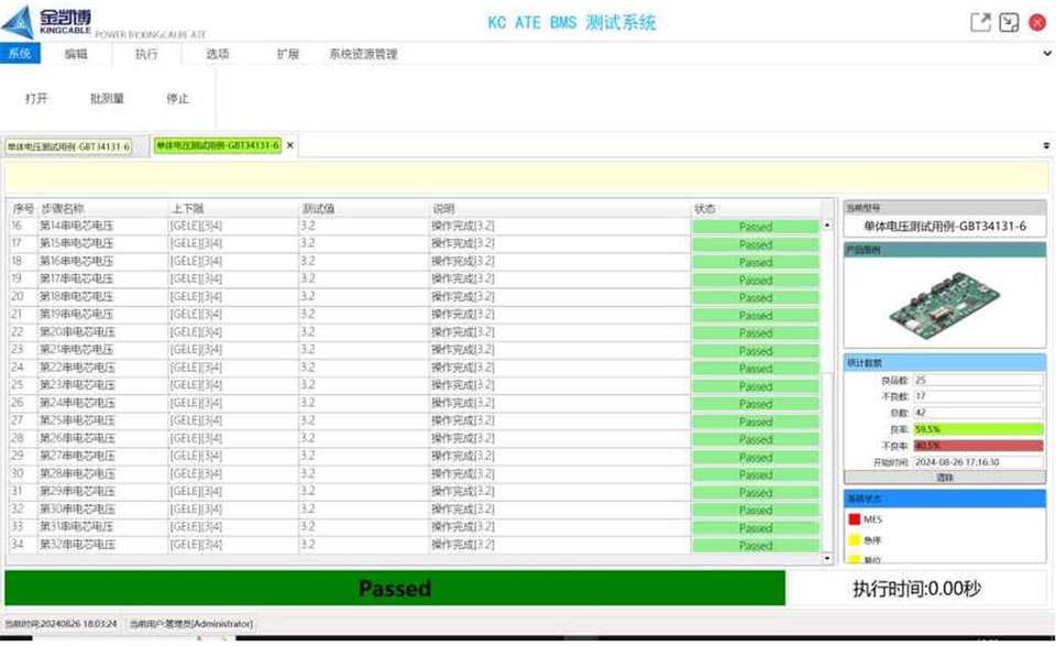
Software Display

Application Areas
Electric locomotive power battery BMS research and development, production and testing;
Photovoltaic energy storage battery BMS research and development, production testing;
Industrial and commercial energy storage system BMS research and development, production testing;
Microgrid energy storage battery BMS research and development, production testing, etc.
Technical Parameters
Function | Equipment Category | Product Features |
Battery characteristics simulation | Battery Simulator | A single unit has a maximum of 36CH , voltage accuracy: 0.01%+0.01%FS , voltage specification: 6V , current specification: 1A/2A/3A |
A single unit has a maximum of 24CH , voltage accuracy: 0.01%FS , voltage specifications: 5V/6V/15V/20V , current specifications: 1A/2A/3A/5A/10A , optional fault simulation | ||
A single unit has a maximum of 12CH , voltage accuracy: 0.01%+0.01%FS , voltage specifications: 5V/6V/15V/20V , current specifications: ±1A/±2A/±3A/±5A/±10A , optional fault simulation | ||
A single unit has a maximum of 24CH , voltage accuracy: 0.01%FS , voltage specification: 6V/15V/20V , current specification: ±1A/±2A/±3A/±5A , optional fault simulation | ||
Total voltage simulation | High voltage DC power supply | Half 19"/1U , with 2000V , 3000V voltage specifications, voltage accuracy can be achieved: 0.05%FS |
Total current simulation | Low voltage and high current power supply | 10V specification products, the maximum single-machine current can achieve 20kA , current accuracy: 0.1%+0.1%FS |
Electronic Load | The maximum single-machine current can reach 5kA , current accuracy: 0.05%+0.0.5%FS | |
Voltage range: 0~1200V ; Power range: 1~600kW ; Voltage accuracy: .025%+0.025%FS ; Current accuracy: 0.05%+0.0.5%FS ; Built-in multiple practical test functions | ||
BMS power supply | BMS power supply | Half 19"/1U , with 36V and other voltage specifications, power levels include 600W/900W/1200W/1500W/1800W |
Total current direction switching | Current commutation box | Current specifications include: 200A/600A/1000A/1500A/2000A/3000A |
Current sensor signal simulation | Current Sensor Simulator | 4CH/ voltage output range: ±5V , ±200mV/0.02%+0.02%FS ; current output range: ±200mA/0.05%+0.05%FS , channel isolation |
Temperature simulation | Thermocouple Temperature Simulator | Up to 24CH optional, output to cold end voltage: -15mV ~ +85mV , resolution 1.6uV , 0.1%+10uV |
NTC Temperature Simulator | 8CH , 0Ω ~16MΩ, resolution 1Ω, 0.1%+1Ω | |
Thermal resistor temperature simulator | 12CH , analog types: PT100/PT200/PT500/PT1000/Cu50/Cu100 , multiple temperature resolutions available | |
Sensor simulation | Pressure, flow, level simulator | 4CH/ voltage output range: ±5V , ±200mV/0.02%+0.02%FS ; current output range: ±200mA/0.05%+0.05%FS , channel isolation |
Insulation withstand voltage simulation | Insulation resistance card | 200k ~61MΩ , resolution 1kΩ , 1%+1kΩ , withstand voltage 1000V , total power 3W |
Up to 12CH optional, 50Ω ~ 111MΩ , resolution: 50Ω , withstand voltage 2000V , accuracy 1%+50Ω , open circuit resistance >100MΩ , 2U chassis | ||
I/O Switching | Relay Card | 24CH , maximum switching power: 60AV/24W |
I/O signal simulation and detection | I/O Cards | 16CH DI/16CH DO , input / output isolation, input voltage: 12V ~ 32V , output voltage: 24V ; input and output frequency: 0-100kHz , duty cycle step 1% , drive current: 100mA MAX |
16CH DI ( 25MHz ), 16CH DO ( 50MHz ) , output: 3.3V@24mA or 5V@32mA , input: 3.3V or 5V |
Our BMS testing solution can meet more than 90% of BMS testing needs on the market
For customized test items, please contact us to get more information...
—————————————————————————————————————————————————————————
Hello! The above product information only lists some of the main test functions. All items supported by the equipment are not listed in detail here.
If you need to obtain customized solutions or company introduction materials, please contact mobile phone & WeChat: +86 18033069200
Click the picture below to view more customer cases