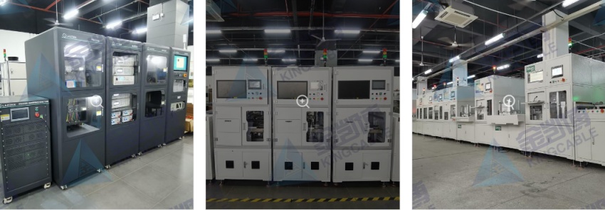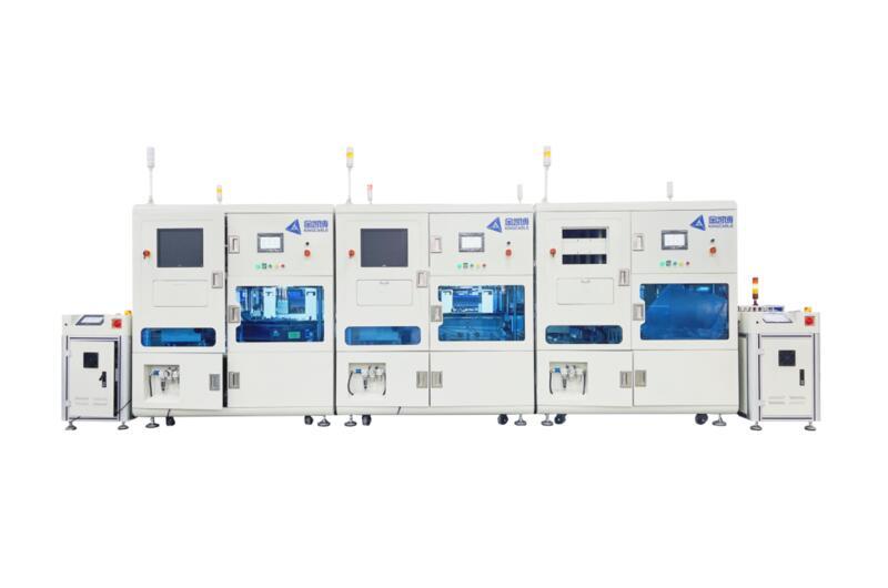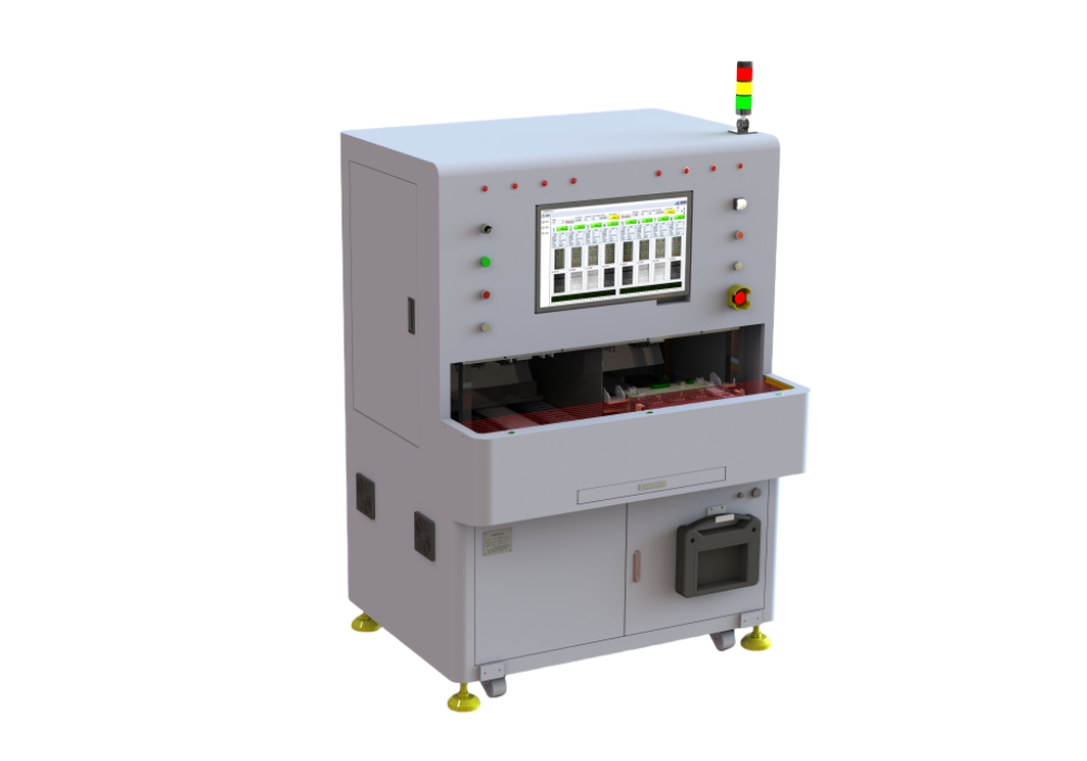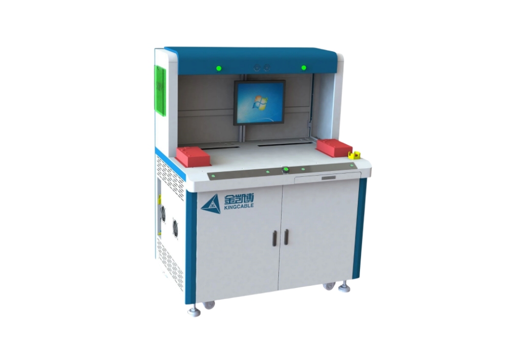
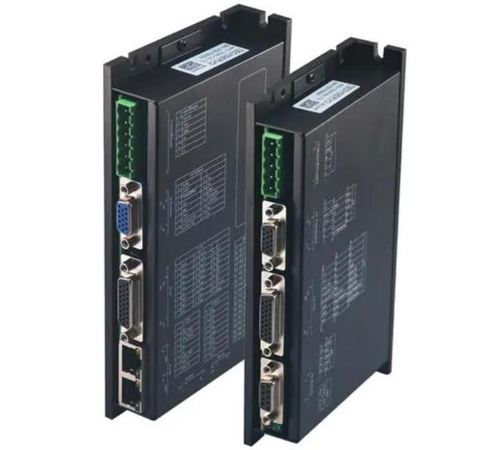


Equipment Introduction
Expand according to product interface;
Analog product input, channels can be expanded as needed;
Detect level input threshold and impedance;
lo protection current test;
Single machine communication and cascade function test;. Automatically determine the balance of product output;
Automatically detect missing code segment, reverse installation, shadow, dim brightness and other display functions;
Can detect the voltage, current, power, THD and other electrical parameter values of the driver current output (U, V, W);
Can count the A, B, Z phases of the servo encoder output differential pulse count and automatically determine;


Test Items
Serial number | Test subjects | Test items | Test Method | Criteria |
1 | Cooling fan | Start and Stop | 1. Aim the anemometer at the fan | The anemometer reading should be within the predetermined range |
2 | 7-segment LED display | Display different characters | The driver controls the display 0~7 respectively | LED displays the correct value |
3 | USB | Basic electrical properties | The test device is connected to USB and reads the 5V power supply voltage and current | The 5V power supply voltage should be within the predetermined range and the current should be less than the predetermined range. |
4 | USB | Power short circuit protection | 1. Short the USB5V power supply and read the 5V power supply | 1. When short-circuited, the current should be less than the preset value |
5 | USB | Connection Status | 1. Disconnect USB, power on, test the device and driver to determine the USB connection status. | 1. Both the driver and the test device should be able to correctly determine the USB connection status. |
6 | USB | Data reading and writing | 1. Read software version | The software version number and drive number read back should be correct. |
7 | Control AC power supply (L1C/L2C) | Threshold voltage | Gradually increase the voltage and record the input voltage at which the driver can enter the working state. | The critical working voltage should be less than the preset value |
8 | Control AC power supply (L1C/L3C) | Standby current | Record the current value in standby mode when the input is 220V. | The standby current should be less than a predetermined value. |
9 | Power AC power supply (L1/L2) | Power on | 1. Before switching on, ensure that the bus capacitor voltage is lower than | 1. The charging time should be within the preset range. |
10 | Power AC power supply (L1/L2) | Natural discharge | After disconnection, in standby mode, record the time it takes for the DC bus capacitor to discharge to the specified voltage. | The discharge time should be within the predetermined range. |
11 | Power AC power supply (L1/L2) | Working discharge | After power failure, when UVW continues to output the specified current, record the time it takes for the DC bus capacitor to discharge to the specified voltage. | The discharge time should be within the predetermined range. |
12 | Discharge resistor | Connection Status | 1. Disconnect the discharge resistor and the driver determines the connection status. | The driver should be ready to determine the connection status. |
13 | Discharge resistor | Working status | When the discharge resistor is connected | 1. The driver should be ready to determine the connection status. |
14 | Motor power supply (UVW) | Standby mode | After the driver is enabled, it outputs zero power. The driver and test equipment read the three-phase current. | All three-phase currents should be less than a certain predetermined value. |
15 | Motor power supply (UVW) | Load status | After the driver is enabled, it outputs a voltage of a specified frequency and amplitude, and the driver and test device read the three-phase current. | 1. The three-phase current frequency error should be within the predetermined range. |
16 | Motor power supply (UVW) | Short circuit protection | 1. After the driver is enabled, it outputs a voltage of a specified frequency and amplitude to short-circuit two phases. | The drive should trigger the overcurrent hardware protection. |
17 | EtherCAT | Connection Status | 1. Disconnect EtherCAT, power on, and test the device and driver to determine the USB connection status. | Both the test device and the driver should be able to accurately identify the connection status. |
18 | EtherCAT | Data reading and writing | Perform a read-write-readback operation on a variable | The data read back should be correct. |
19 | Encoder | Basic electrical properties | The test device is connected to the encoder to read the 5V power supply voltage and current | The 5V power supply voltage should be within the predetermined range and the current should be less than the predetermined range. |
20 | Encoder | Power short circuit protection | 1. Short the encoder 5V power supply and read the 5V power supply | 1. When short-circuited, the current should be less than the preset value |
21 | Encoder | Connection Status | 1. Disconnect the encoder, power on, test the device and driver to determine the USB connection status. | The drivers should be able to accurately identify the connection status. |
22 | Encoder | Data reading and writing | Read and write the electronic nameplate information in the encoder. | Electronic nameplate information can be read and modified correctly. |
23 | EEPROM | Data reading and writing | Read and write data in EEPROM | EEPROM data can be read and modified correctly. |
24 | Built-in temperature sensor | Temperature reading | Read and write initial temperature after power on | The initial temperature should be within the predetermined range |
25 | Built-in temperature sensor | Temperature rise reading | After the driver works at the specified load for a specified time, read the temperature | The temperature rise should be less than the preset value. |
26 | Digital input | Input polarity | The input common terminal is connected to 30V and 0V respectively, and each channel is connected to the high and low signals of the test device. | When different input common terminals are connected, the driver reads the correct input. |
27 | Digital input | High-speed input current limiting | Testing input current limiting for high-speed channels | The current should be less than the predetermined value. |
28 | Digital input | Input Threshold | The test device adjusts the input voltage value of each channel and records the voltage obtained by the driver when the input level is flipped. | The input threshold should be within a predetermined range. |
29 | Digital input | Input Impedance | Each input channel inputs a high level, and the test device tests the input current. | The current should be less than the predetermined value. |
30 | Digital input | Input Response | For fast input channels, test the pulse response | The driver receives the same number of pulses. |
31 | Digital output | Output polarity | The output common terminals are 24V and 0V respectively, and the driver outputs high and low levels on each channel. | Under different input common terminal access conditions, the test device can read the correct output. |
32 | Digital output | Output Capacity | The digital output terminal of the driver is connected to a standard load, and the driver outputs high and low levels on each channel. | The output current read by the test device at each output channel should be within the predetermined range. |
33 | Digital output | Short circuit protection | 1. Short-circuit the driver digital output and each channel outputs a high level. | Measure the output current of each output channel, which should be less than the preset value. |
34 | High-speed differential pulse input | Pulse input | 1. Select three pulse input modes, and the test device outputs pulses of a certain length according to the highest allowable frequency. | The driver should be able to get the pulse length correctly. |
35 | Low speed OC pulse input | Pulse input | Three pulse input modes are selected, and the test device outputs pulses of a certain length at the highest allowed frequency. | The driver should be able to get the pulse length correctly. |
36 | Pulse output | Pulse output | The driver outputs A/B/Z pulses of a certain length according to the maximum allowable frequency and the minimum Z pulse width. | The test device should be able to correctly read the output pulse number and Z pulse number. |
37 | RS485 | Data reading and writing | 1. Communication baud rate 115200 2. Read software version 4. Modify the written variables 5. Read back verification | 1. Reading and writing the variables used for testing should be normal and the data should be correct. |
38 | ABZ Encoder | Basic electrical properties | The test device is connected to the encoder to read the 5V power supply voltage and current | The 5V power supply voltage should be within the predetermined range and the current should be less than the predetermined range. |
39 | ABZ Encoder | Power short circuit protection | 1. Short the encoder 5V power supply and read the 5V power supply | 1. When short-circuited, the current should be less than the preset value |
40 | ABZ Encoder | Connection Status | 1. Disconnect the encoder, power on, test the device and driver to determine the USB connection status. | The drivers should be able to accurately identify the connection status. |
41 | STO | Working status | 1. Connect the STO terminal, the host computer has no error alarm, and the drive can be enabled normally 2. Disconnect the STO terminal and the driver will be disabled. If the STO terminal is not connected, the driver cannot be enabled. |
—————————————————————————————————————————————————————————
Hello! The above product information only lists some of the main test functions. All items supported by the equipment are not listed in detail here.
If you need to obtain customized solutions or company introduction materials, please contact mobile phone & WeChat: +86 18033069200
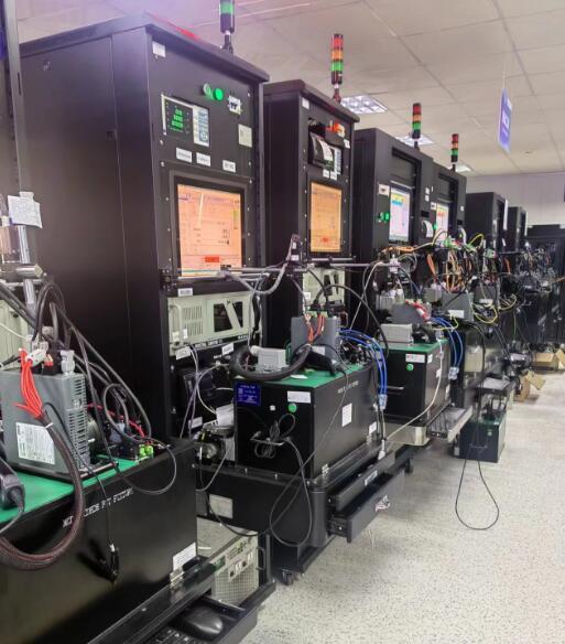
Click the picture below to view more customer cases